-
Your shopping cart is empty!

Your shopping cart is empty!

![]() MKS DroneCAN Intergration Video >>
MKS DroneCAN Intergration Video >>
![]() DroneCAN start : https://youtu.be/NP5_RIoX8Bo
DroneCAN start : https://youtu.be/NP5_RIoX8Bo
https://github.com/DroneCAN/gui_tool
https://zubax.com/products/babel
Connect the Servo to the convert board and the computer.
Then open the DroneCAN GUI Tool to start.
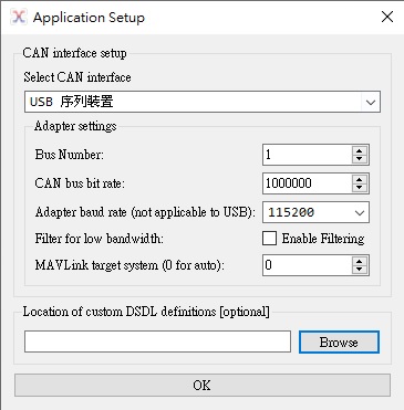
1-1.1 Select CAN interface set to “USB serial device” (USB序列裝置).
1-1.2 CAN bus bit rate set to default “1000000”.
 |
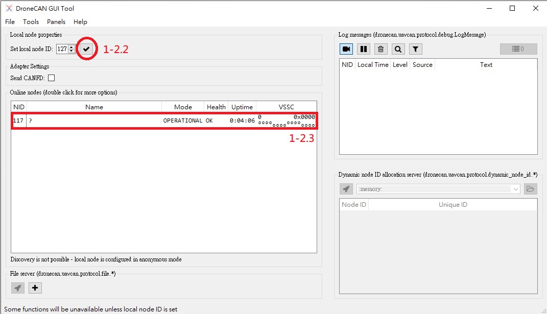
1-2.1 Enter the DroneCAN GUI Tool interface.
1-2.2 Press ![]() then start to read all the node device(Servo) data.
then start to read all the node device(Servo) data.
1-2.3 Double click the device to display the node(Servo) Properties.
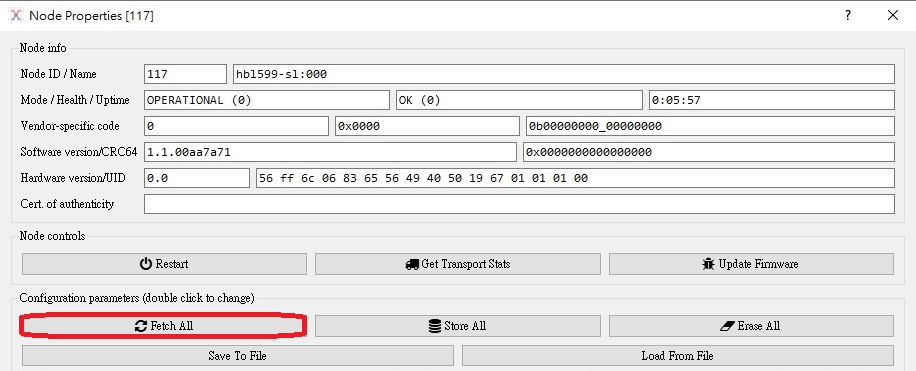
1-3.1 Press the “Fetch All” to display the Servo parameter.
2. DroneCAN interface
|
2.1 |
subcriber |
|
|
2.2 |
publisher |
|
|
2.3 |
publisher |
|
|
2.4 |
publisher |
3. Application-level functions
|
3.1 |
RPC-service |
|
|
3.2 |
RPC-service |
|
|
3.3 |
RPC-service |
|
|
3.4 |
RPC-service |
|
|
3.5 |
RPC-service |
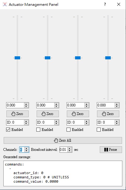
4.1 ArrayCommand
![]() Actuator Panel : https://youtu.be/hmN6ZP9EF-Y
Actuator Panel : https://youtu.be/hmN6ZP9EF-Y
The control command of the Servo.
Command type 0 : UNITLESS
|
Command encoding : -1 ~ 1 |
-60.0°~+60.0° (The default travel Angle of the Servo) |
Using the Panels->Actuator Panel to command the Servo.
Please set the command update rate to 0.01sec, Servo will work more smoothly due to the high command update rate.
4.2 actuator.Status
You can use the actuator.Status feedback data to monitor the physical status of Servo.
|
Function |
Type |
unit |
|
actuatorID |
integer |
|
|
position |
float |
° [degree] |
|
force(torque) |
float |
Kg.cm |
|
speed |
float |
°deg/sec |
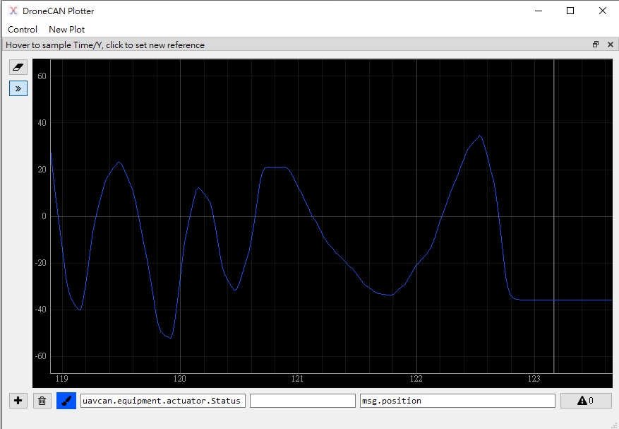
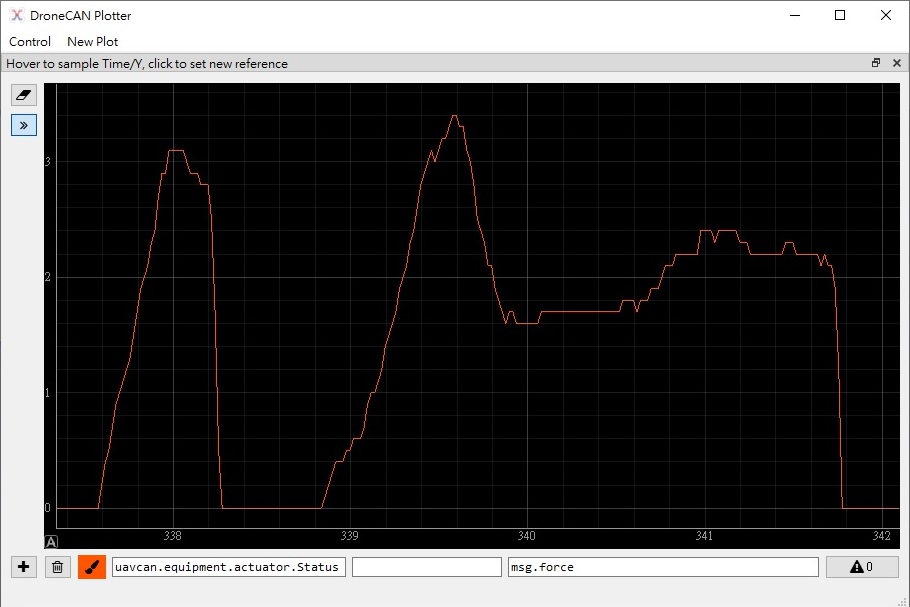
Using the Tools->Plotter to add the graphics of Y-T axis.
You can see the message type there has the actuatorStatus Option.
Expression to the plot by typing “msg.” and you will see the all actuatorStatus functions.
![]() Position Feedback : https://youtu.be/hmN6ZP9EF-Y
Position Feedback : https://youtu.be/hmN6ZP9EF-Y
![]() Force&Current Feedback: https://youtu.be/6MiqRyRupKQ
Force&Current Feedback: https://youtu.be/6MiqRyRupKQ
*Position Feedback graphic
* Force Feedback graphic
4.3 power.CircuitStatus
![]() Force&Current Feedback: https://youtu.be/6MiqRyRupKQ
Force&Current Feedback: https://youtu.be/6MiqRyRupKQ
![]() Voltage&Error flag Feedback : https://youtu.be/DIUP535PmgQ
Voltage&Error flag Feedback : https://youtu.be/DIUP535PmgQ
You can use the power.CircuitStatus feedback data to monitor the electronic status of Servo.
|
Function |
Type |
unit |
|
voltage |
integer |
1 unit = 0.1 V |
|
current |
integer |
1 unit = 0.1 A |
|
error_flags |
integer |
1= over voltage 9V 2= under voltage 5V 4= over current |
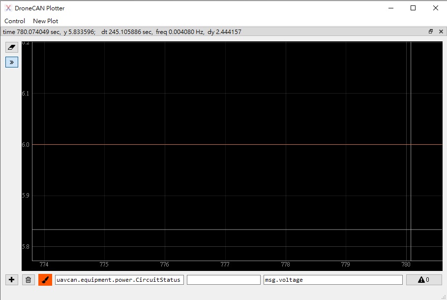
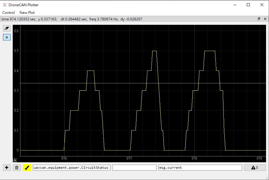
Using the Tools->Plotter to add the graphics of Y-T axis.
You can see the message type there has the CircuitStatus Option.
Expression to the plot by typing “msg.” and you can see the all CircuitStatus functions.
* voltage Feedback graphic
* current Feedback graphic
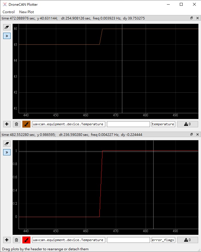
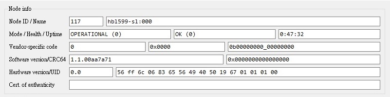
4.4 device.Temperature
You can use the device.Temperature feedback data to monitor the internal temperature of the Servo.
Here has a special function. When the Servo over heating, it will actively feedback the error_flags. You can set the over_heating value by using param.GetSet functions No.24 temperatureLimitVal.
|
Function |
Type |
unit |
|
deviceID |
integer |
0 ~ 255 |
|
temperature |
integer |
1 unit = 1 °C |
|
error_flags |
integer |
over heating |
* TemperatureProtect Active over 45°C
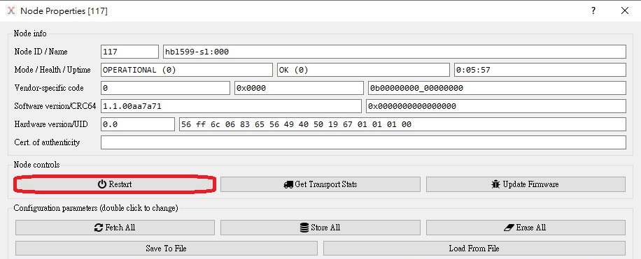
5.1 GetNodeInfo
|
Servo unique ID |
12 byte |
|
Date of manufacture |
3 byte, date=[1byte], month=[1byte], year= 2000 + unit8 [1byte] |
|
Serial number |
1 byte [0~127] |
|
nodeName (Servo Type) |
16 byte |
5.2 NodeStatus
|
operatingtime, mode, health |
![]()
5.3 param.GetSet
List Update: 2023.11.01
|
|
Functions |
Description |
| 0 |
actuatorID |
Servo Control, Channel ID |
| 1 |
NodeID |
Servo setting, status feedback ID |
| 2 | neutralpoint | [1 unit = 0.1°deg] |
| 3 | cmdReversed | True:rotate reversed False:Normal |
| 4 | Boost |
The step of the Motor startup. The larger of the value, the motor startup step will more powerful. Larger value may cause the Servo jitter. |
| 5 | deadband |
Control resolution of the Servo. Too small may cause the Servo make noise. Too large the Servo control resolution will be rough. The deadband is a band of input values in the domain of a transfer function in a control system or signal processing system where the output is zero (no action occurs). |
| 6 | anglezoom(CCW) | 100 unit = 1.0. Magnification |
| 7 | anglezoom(CW) | 100 unit = 1.0 Magnification |
| 8 | IntergralCoe(Ki) |
When the Servo is statically subjected to a larger external load, the servo angle may slightly deviate from the command position. Setting this function can increase the Servo’s strength of bearing the external load in a static status to enable the Servo arrive at the commanded position accurately. If the Ki value is larger, the servo angle may go beyond the command position when the external load disappears instantaneously. |
| 9 | Brakecurve(Kd) |
The Servo will slow down when about to reach the command position. To reduce the inertial force of the mechanically. The lower value means the curve is sharp. The larger value means the curve is soft. |
| 10 | Softstartcurve(Acceleration) |
The lower value means the curve is soft. The larger value means the curve is sharp. |
| 11 | BootupSpdLimitVal |
The value of the Servo speed when startup. 1 unit = 0.01° sec/60°deg 0=off |
| 12 | SpeedLimitValue |
1 unit = 0.01 sec/60°deg 0=off
|
| 13 | BootupMode |
The Servo will action when Startup with no command : 0 = Holding on current command position 1 = Rotate to #14 BootupAngle position 2 = Servo trun into Brake mode 3 = Servo trun into release mode |
| 14 | BootupAngle |
[1 unit = 0.1°deg] Actived when #1BootupMode setting = 1. [Max. angle position will limit by different Servo Type.] |
| 15 | cmdLostMode |
When the command is lost, the Servo will action according to the following settings: 0 = Hold on last command position 1 = Rotate to the specific position as #17 cmdLostAngle 2 = Enter into Brake Mode 3 = Enter into Release Mode
|
| 16 | cmdLostTimeout |
1 unit = 0.1 seconds |
| 17 | cmdLostAngle |
[1 unit = 0.1°deg] position. Actived when #15 cmdLostMode setting = 1. [Max. angle position will limit by different Servo Type.] |
| 18 | CurrentProtectActivation |
True:On False:Off |
| 19 | ThresholdCurrent |
1 unit = 0.1 A When the Servo operating current over #19 ThresholdCurrent. and over #20 OverCurrentDuration seconds. The Servo will limit the max. current to #21 CurrentLimitVal. |
| 20 | OverCurrentDuration |
1 unit = 0.1 seconds |
| 21 | CurrentLimitVal | 1 unit = 0.1 A |
| 22 | temperatureProtectActivation |
True:On False:Off 1. When the Servo temperature is over the set value (°C) of #23 temperatureLimitVal, the Servo output will decrease gradually. 2. When the Servo temperature is lower than the set value (°C) of #23 temperatureLimitVal, the Servo output will be back to normal. |
| 23 | temperatureLimitVal |
lower than the set value (The protection mechanism will activate when set #22 temperatureProtectActivation as True. °C) of #23 te |
| 24 | actuatorPublishHz |
The transmission rate of Actuator.status. 1 unit = 1Hz, 0=off |
| 25 | CircutPublishHz |
The transmission rate of Circuit.status. 1 unit = 1Hz, 0=off |
| 26 | TemperaturePublishHz |
The transmission rate of Device.Temperature. 1 unit = 1Hz, 0=off |
| 27 | CAN-Bitrate |
CANbus Bitrate setting. After change the setting will required to reboot to renew the CAN-Bitrate. 0= 1M 1= 500k 2= 250k 3 = 125k 4 = 50k |
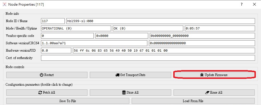
5.4 RestartNode
![]() NodeID Restart : https://youtu.be/QKeApZcIXLY
NodeID Restart : https://youtu.be/QKeApZcIXLY
You can use the “RestartNode” to restart the Servo without unplug from the power to renew nodeID when you changing the Node ID by using the param.GetSet.
5.5 file.BeginFirmwareUpdate
The MKS DroneCAN Servo can be easy to update the Firmware by using DroneCAN GUI tool. It can make sure you will have the newest Servo Firmware when you have already own the Servo for a while.
* To ensure the safety of in-flight, the firmware update can only be activated within 30 seconds after the Servo startup. When the Servo startup after 30 seconds the firmware update cannot be performed.
※Notice: Firmware update can only be updated under CAN bitrate 1M (can be set up in 27.mks.servo.CAN-Bitrate).
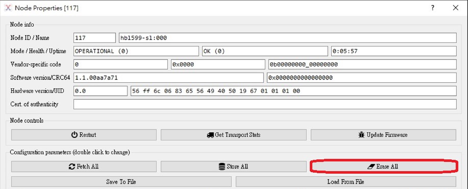
5.6 GoBack to Default
You can use the “Erase All” to set the Servo all parameter back to the default.